Cable routing and trenches
How DC, AC and medium-voltage runs are routed, what the conductor and trench totals mean, where they are reported, and how hand-drawn trenches change later runs.
Cable routing turns a placed layout into cable lengths you can cost: string cables from the tables to the inverters, feeders from the inverters onward, and medium-voltage runs from the control rooms to the main control room. It also reports trench lengths, which are a different quantity from conductor lengths and are reported separately.
None of it happens unless you ask for it. Calculate cables is off by default, and with it off no route is computed at all.
Turning cable calculation on
The option is the first row of the Cables card on the Electrical tab — see Cables for the card. Ticking it raises the Cable Calculation — Performance Notice: cable calculation can take a long time on large or complex layouts. The buttons are Enable Now and Not Now (Recommended), and the recommended one is the default.
Take the recommendation. The useful sequence is:
Generate without cables first
Leave Calculate cables unticked and click Generate Layout. You get the tables, the capacity, the control rooms and the arresters quickly, which is what you need in order to judge whether the layout is right at all.
Fix the layout inputs
Row pitch, table configuration, the capacity block, obstructions — settle all of it while runs are fast. Cable routing on a layout you are about to change is work thrown away.
Tick the option and run once more
With the layout settled, enable cable calculation for the final run and read the lengths. Cable routing is the slow step on a large plant; on very large plants the application switches to a fast geometric estimate so that generation stays workable.
With cable calculation off you still get the inverter and monitoring-box counts — those come from the string arithmetic, not from routing — and every cable and trench row of the Summary view reads a dash. See Inverter settings for the string limits that set those counts.
The three DC allowances
Under the tick, the same card carries three allowances that turn a routed string-cable length into the figure a bill of quantities expects. All three apply to fixed-tilt tables only, and none of them is kept in a project file.
| Field | Default | Range | What it adds |
|---|---|---|---|
| Inter-module lead | 0.5 | 0.0–2.0 m/module | The string cable between neighbouring modules, counted once per string |
| String return run along table | on | — | One conductor running back along the table so both leads exit at the same end. Untick for U-wired strings whose leads already exit the same end |
| DC cable slack | 10.0 | 0.0–30.0 % | Slack and wastage added to the DC string-cable total |
What is routed in each electrical design
The inverter design you chose at launch decides which legs exist. A conductor multiplier is applied to each leg, because a route drawn once on the plot is not the same as the cable you buy.
| Leg | Route | Counted | Why |
|---|---|---|---|
| String cables | Each table to its inverter | × 2 | A DC string needs a positive and a negative conductor over the same path |
| AC cables | Each inverter to the nearest ICR | × 1 | A three-phase AC feeder is counted once along its route |
ICR is the inverter control room — the building the AC feeders terminate in. Each inverter is routed to the nearest one, so the ICR positions influence the AC total as much as the inverter positions do.
Summary rows: String DC cable (m) for the string cables and AC cable to ICR (m) for the AC feeders.
Both designs then have medium-voltage cables from the control rooms onward, which work the same way in either.
Where the inverters go
Inverters — or string monitoring boxes, in a central-inverter design — are not placed on a fixed grid. They are grouped from the positions of the tables themselves: the tables are gathered into spatial clusters, and one inverter serves each cluster, so a unit sits inside the group of tables it collects rather than at an arbitrary point.
Each one is then sited in the gap band between two rows — the pitch gap that already exists for shading — so the inverter does not cost you a table. A placed string inverter is drawn as a 2 m east–west × 1 m north–south marker.
How many there are is set by the string limits on the inverter card, not by the routing.
How a route is found
Three properties describe the routing, and the third one has a consequence worth being honest about.
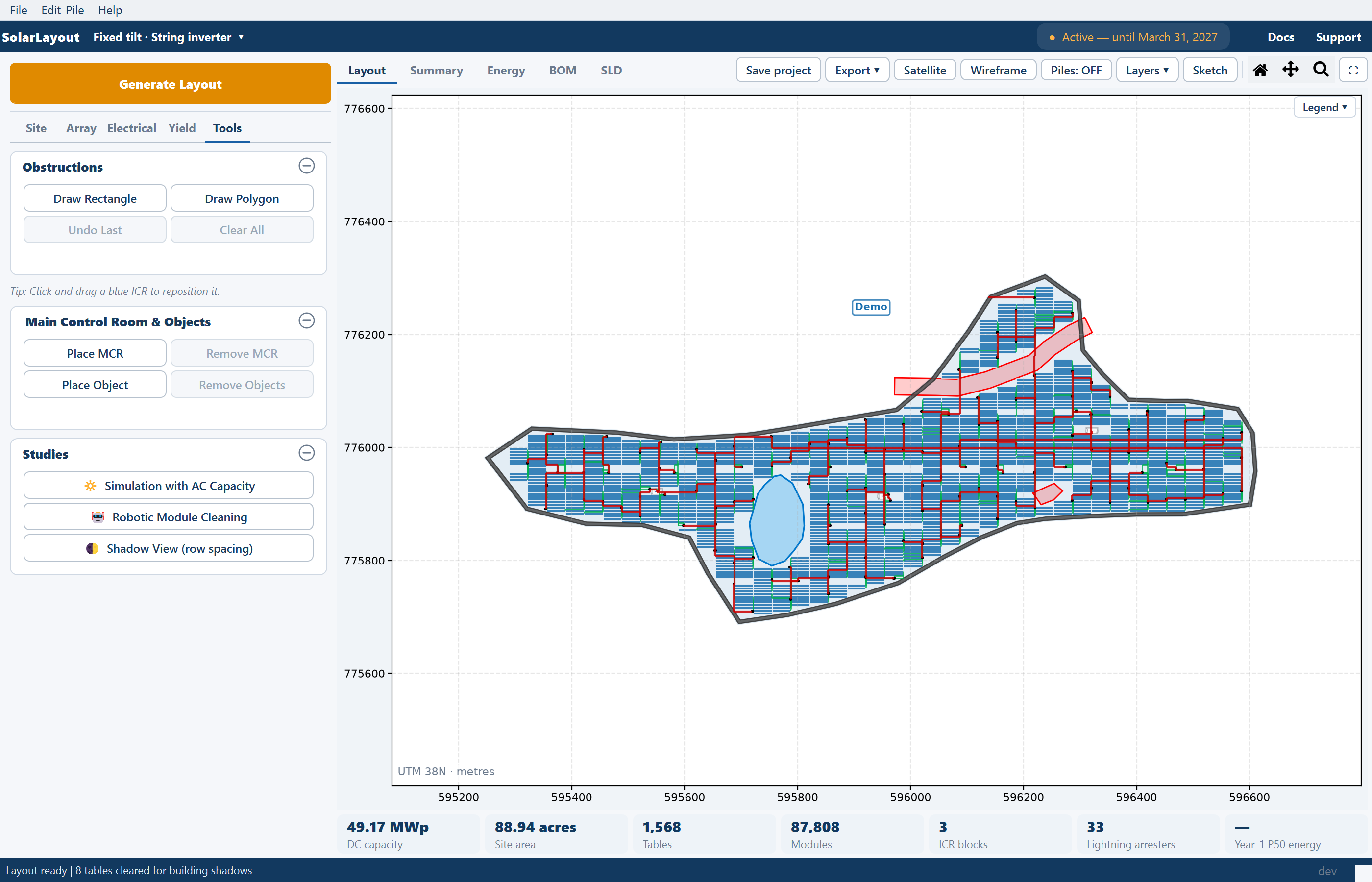
Right angles only. Every route is made of horizontal and vertical segments. There are no diagonals, because a cable trench across a solar plant follows the row and column grid the plant is built on — that is how it is dug and that is how it is cabled.
Every candidate is checked against the usable area. A route is only accepted if it stays on ground that is actually available: it may run inside the perimeter road band, but it never leaves the plant fence, and it does not cross a water body, a line corridor, an obstruction or excluded terrain. See Obstructions.
A series of routing patterns is tried in turn. The application works through a fixed sequence of right-angled path shapes between the two endpoints and takes the first one that validates against the usable area. If none of them validates, it falls back to a last-resort route that is guaranteed to return something connected.
Because the fallback always succeeds, a route is always produced. On an awkward boundary — a narrow waist, a deep notch, a corridor cutting the plant in two — that last-resort route can be considerably longer than the run an engineer would draw, and it is still counted in the totals. Switch the cable layers on and look at the long runs before you cost them.
Segments that several inverters share through the same corridor are counted once. Routing many inverters toward the same control room naturally puts them on a common path for the last stretch, and that stretch is one trench, not one per inverter.
Medium-voltage cables
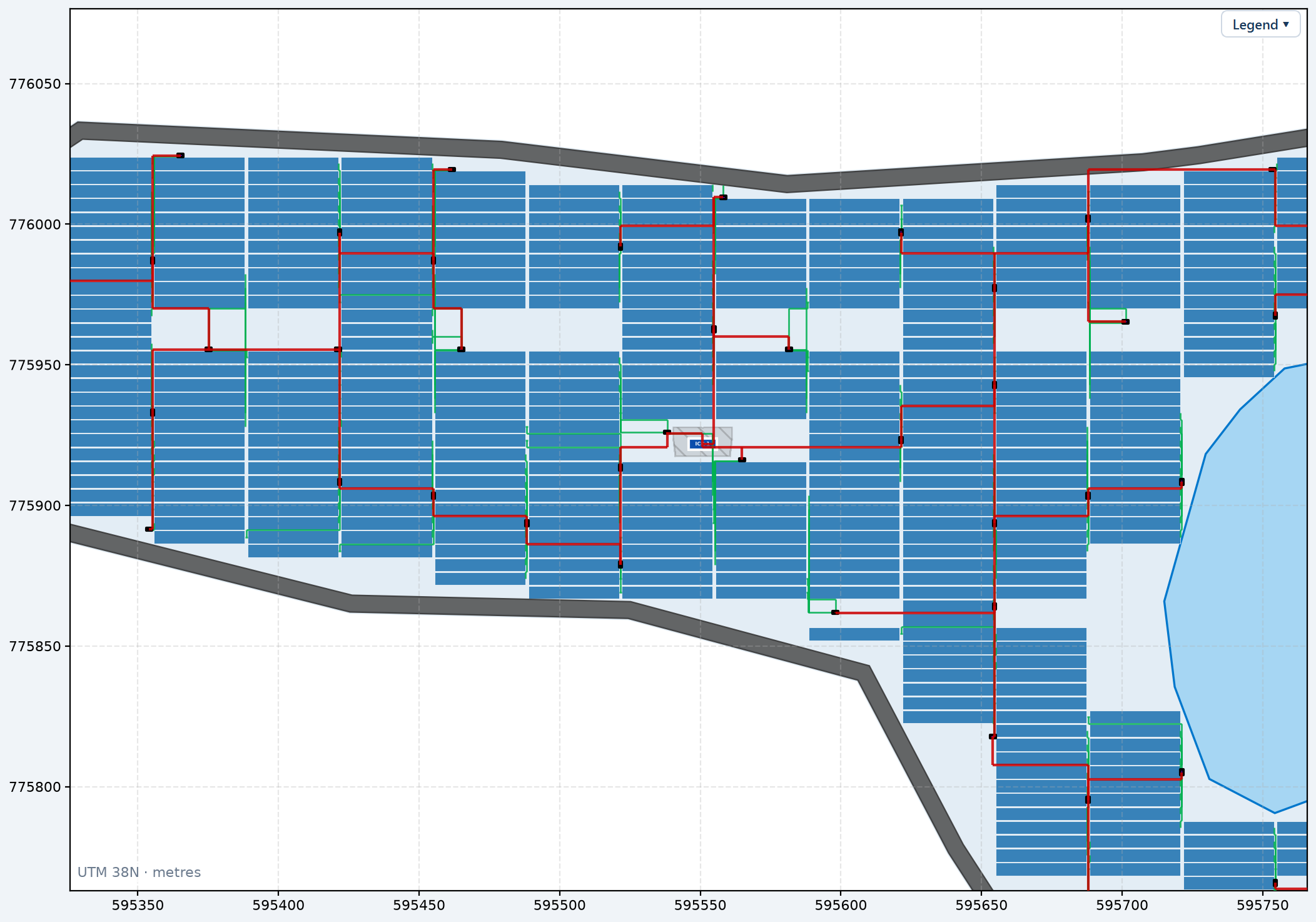
Medium-voltage — MV — cables run from each inverter control room to the main control room. They are not routed one by one. All the control room exit points and the main control room entry point are connected as a single shared-trunk network, so control rooms that are near each other feed into a common trunk instead of running parallel lines across the same ground to the same destination. That is both what gets built and what costs less.
Each branch of the network carries a termination allowance of 10 m, covering the terminations at its ends over and above the routed distance.
Nothing medium-voltage is routed until the main control room is placed —
there is no destination before that — and placing it routes nothing either.
The medium-voltage cables are routed on the next Generate after
Place MCR, with Calculate cables on. Until then the hint under the
placement buttons reads "MCR placed. Enable 'Cable Calc' and regenerate layout
to route MV cables.", the MV row of the Layers popover has nothing to show and
the Summary's MV cable (m) reads —. After that run the status line adds
"| MV cable: n m". See
Main control room, substations and street lights.
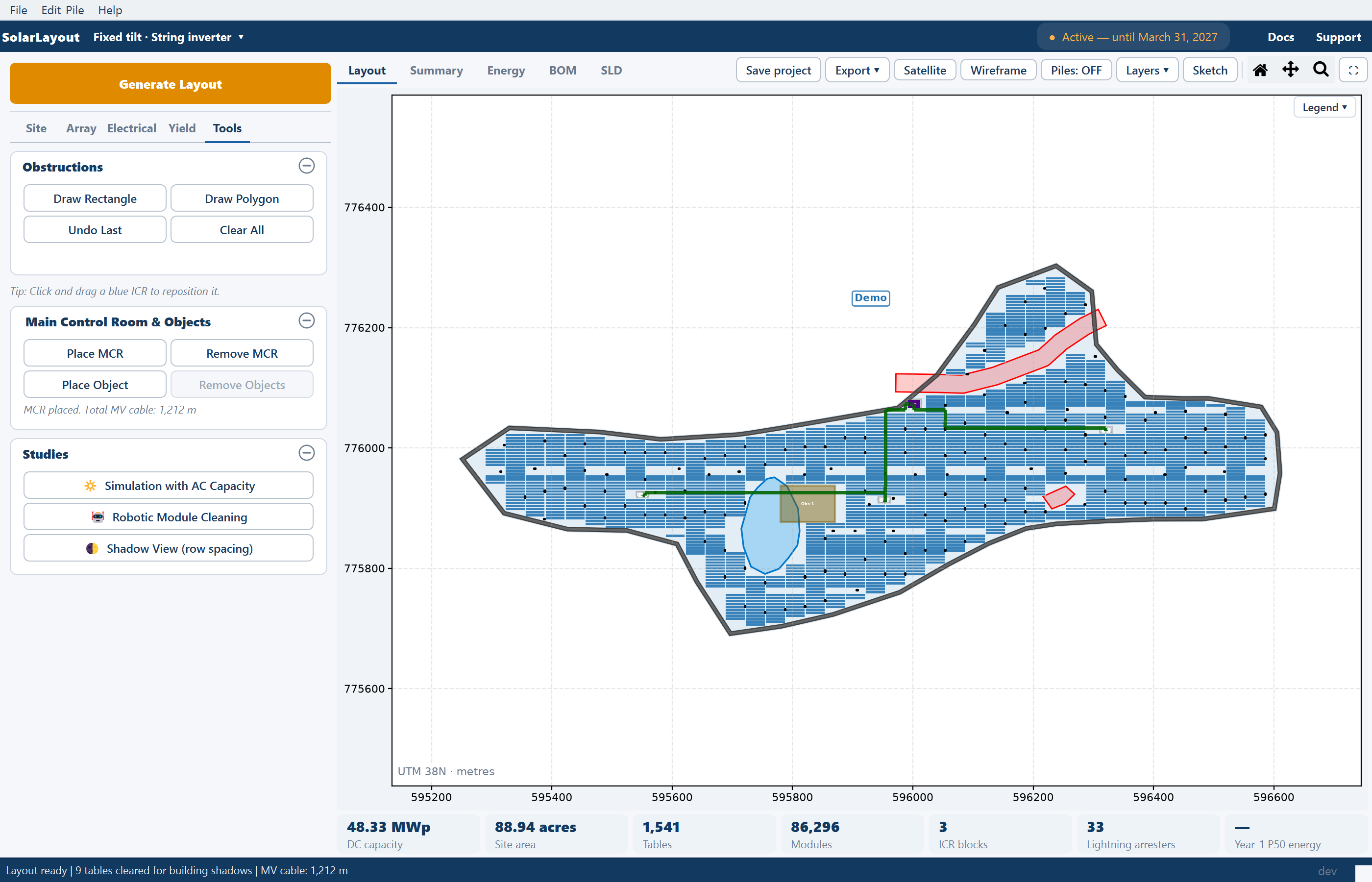
The Summary view reports the medium-voltage conductor length in MV cable (m).
Trenches and conductors are different totals
This is the distinction to carry into a cost estimate, and the Summary view reports both so you never have to guess which one a number is.
- A conductor total is the length of cable, including the multipliers above: a DC leg counted twice, an AC feeder counted once.
- A trench total is the length of physical trenching — the de-duplicated path length for that cable type. Where several cables share one route, the trench is counted once.
So the conductor total is always the larger of the two, often by a lot. Neither number is wrong; they answer different questions. Conductor length prices the cable drum. Trench length prices the excavation, the sand bedding, the tiles and the backfill.
The CABLES group of the Summary view carries them together:
| Summary row | What it reports |
|---|---|
| String DC cable (m) | String cable conductor length |
| AC cable to ICR (m) (string-inverter design) | AC feeder conductor length, inverter to control room |
| DC cable to central inverter (m) (central-inverter design) | DC trunk conductor length, monitoring box to control room |
| MV cable (m) | Medium-voltage conductor length |
| DC trench (m) | DC trench length, de-duplicated |
| AC trench (m) | AC trench length, de-duplicated |
| MV trench (m) | Medium-voltage trench length, de-duplicated |
Every row is defined in Summary rows.
The exports that carry the cabling
Two items of the Export ▾ menu go further than the Summary view:
- Export Cable Schedule (Excel) is the document to issue to a contractor: a workbook with one sheet per ICR block, listing the DC strings from each table row to its inverter or monitoring box and the AC or DC-trunk feeders, with recommended conductor sizes. It is available after any layout, but the lengths are only real when cables were calculated.
- Export Detailed Project Report — the Word document — carries the inverter and cable summary on its design summary page, broken down per control room. The layout drawing in the report hides the cables. See The project report.
The inputs that move the cable totals
Cable lengths are an output, but they are an output of a small number of decisions. If a total looks wrong, these are the fields to look at rather than the routing:
| Input | What it changes | Effect on the cabling |
|---|---|---|
| ICR Block | The number of inverter control rooms | More, smaller rooms shorten the AC feeders — each inverter routes to the nearest room — and add branches to the medium-voltage network, each with its own termination allowance |
| Max strings per inverter (or per SMB) | The number of inverters or monitoring boxes | Fewer, larger units mean longer string runs to reach each one; more, smaller units mean shorter string runs and more collection points |
| Row pitch | The spacing of the rows | Routes run along and across the row grid, so a wider pitch tends to lengthen the north–south legs of the runs |
| The main control room position | The destination of the medium-voltage network | Sets the whole medium-voltage length. Place it where the export actually leaves the site |
| The three DC allowances | The string-cable total only | Lead, return run and slack are added to the routed string length; they never touch the AC, trunk or MV figures |
Because all of these are settled before routing runs, this is another reason to review the layout first and enable cable calculation last.
A hand-drawn obstruction from the Tools tab re-places the inverters but does not re-measure the cables: the String DC cable (m) and AC cable to ICR (m) rows read 0 until the next Generate. Generate again before quoting lengths.
Drawing and deleting trenches by hand
Automatic routing does not know about the access track you intend to dig along, or the crossing you have already agreed with a landowner. Sketch Mode's CABLE TRENCHES group lets you route by hand.
| Tool | What it does |
|---|---|
| 🟢 DC Trench | Click vertices, right-click to finish: a DC trench |
| 🔴 AC Trench | Click vertices, right-click to finish: an AC trench |
| 🟩 MV Trench | Click vertices, right-click to finish: a medium-voltage trench |
| ✂ Del Trench | Click any cable trench — automatic or hand-drawn — to delete it; the untouched trenches stay as the automatic routing |
Switch 🧲 Snap and ⊾ Ortho on in the contextual bar before drawing a trench you intend to build from. See Sketch Mode.
What manual editing does to the next run
The moment you delete an automatic trench or draw one by hand, the layout's cabling becomes yours. From then on, Generate Layout keeps the current cables instead of re-routing them — on Generate the cable follows your trenches — so your edits survive the next run rather than being overwritten.
The consequence, plainly: once you have edited the trenches, a later change to an input will not re-route the cables. Change the row pitch or move a control room after hand-editing, and the tables move while the cabling stays where you put it.
There is no control that undoes this. Nothing clears manual trench edits and hands the cabling back to automatic routing — not deleting the trenches you drew, not generating again. The one route back to automatically routed cables is to lay the plant out afresh: a new layout, or File ▸ New Project.
The rule is not a defect; it is the only behaviour that makes hand-editing worthwhile. But it does make the order of work matter. Do the hand-editing last, after the inputs have stopped moving, and save the project first so the automatically routed design survives as a file of its own.
Seeing cables on the plot
The three cable rows of the Layers ▾ popover in the Layout view are OFF by default, even after a run that routed them, and the first two are enabled only when cables were calculated. Switch on the ones you want:
| Layers row | Default | Draws |
|---|---|---|
| DC string cables (Tbl→Inv) | OFF | String cables from the tables to the inverters or monitoring boxes — green |
| AC cables (Inv→ICR) — DC cables (SMB→CI) in a central-inverter design | OFF | AC feeders to the control rooms — red — or the DC trunks in a central-inverter design |
| MV cables (ICR→MCR) | OFF | Medium-voltage runs to the main control room — dark green. Needs the main control room placed and cables calculated |
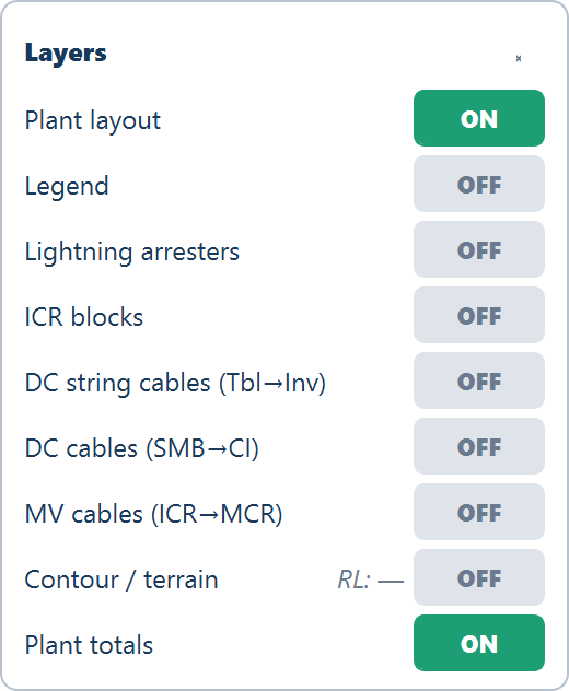
Turning all three on at once over a whole plant is unreadable. Zoom into one block with the mouse wheel, or switch Plant layout off in the same popover to read the cabling on its own. See Views for the popover and the rest of the Layout view's tools.
What reaches the drawing
The CAD export writes each cable type and each trench type to its own layer —
DC_CABLES, AC_CABLES, MV_CABLES, and DC_TRENCH, AC_TRENCH,
MV_TRENCH — and the cable layers are present only when cable calculation
was on for the run. The trench layers carry the automatic and the hand-drawn
trenches alike. Cables are exported to the Google Earth file as well. See
CAD export.
Where to go next
Cables
The Calculate cables option, the performance notice and the three allowances
Main control room and site equipment
Placing the destination every medium-voltage run needs
Inverter control rooms
How many there are, where they sit, and moving one
Summary rows
Every row of the Summary view, group by group
Obstructions
Every kind of ground kept clear of modules — water, buildings, line corridors, terrain, shadows — and how to draw an exclusion by hand from the Tools tab or in Sketch Mode.
Multi-plot sites
One boundary file can hold several separate plant boundaries. Each becomes its own plant, with its own column in the Summary view and its own unit substation.