Inverter settings
How many strings feed one inverter or string monitoring box, what a manufacturer inverter file changes, and where the AC figures land in the Summary view.
The inverter card on the Electrical tab sets how the plant's DC output is collected and converted, how much of it one piece of collection equipment takes, and which manufacturer's machine the AC side is sized from. Its title and its fields follow the inverter topology you chose at launch, because the two topologies collect the strings in different places. See Choosing a design mode for the choice itself.
Whether the cables between the tables and the control rooms are routed and measured is a separate card on the same tab — see Cables.
One definition governs everything on this page. A string is one row of modules within an MMS-Table (MMS — module mounting structure). A fixed-tilt table configured with two rows therefore carries two strings; a half table carries half the strings of a full one. Everything you set here is counted in strings, so the table configuration and this card are two ends of the same decision — see Table configuration.
The card in each design
| Inverter topology | Card title | Where the strings are collected |
|---|---|---|
| String inverter | String Inverter | String inverters distributed across the plant, each converting DC to AC where it stands and sending AC onward |
| Central inverter | SMB – String Monitoring Box | String monitoring boxes distributed across the plant, each collecting strings and passing DC onward |
In a central-inverter design the string monitoring box — SMB — is the collection point. It does no conversion: it gathers the strings assigned to it and sends their combined DC output on to a central inverter, which sits inside an ICR (inverter control room) rather than out in the field. The field equipment and the conversion equipment are separate objects in that design, and the card gives you a field for each.
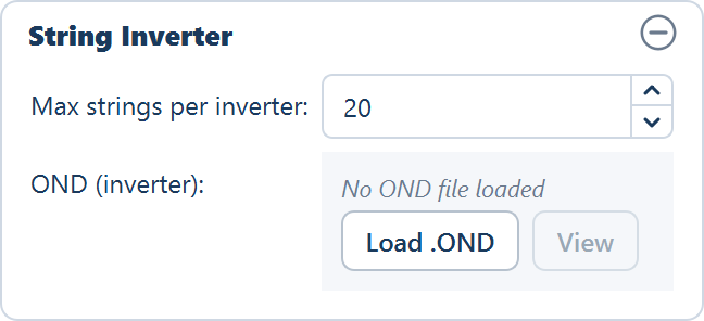
One field and a file row: how many strings one inverter may take, and which inverter file the AC side is sized from.
Maximum strings per inverter
The first field caps how many strings one collection point is allowed to take. The application clusters the placed tables and puts down as many inverters or monitoring boxes as the cap requires, so a lower number means more equipment, each covering a smaller group of tables.
| Field | Default | Range | What it does |
|---|---|---|---|
| Max strings per inverter | 20 | 1–500 | The largest number of string cables one string inverter accepts |
Set this from the inverter or monitoring box you intend to buy, counted the way the application counts: one string per row of modules in a table. The number of modules in that row does not enter into it — a row is a string whether it holds few modules or many. What the row holds decides the string's voltage and current, which is a separate question, settled by string sizing.
The unit count and the DC capacity attached to each unit are reported in the Summary view's ELECTRICAL group — String inverters and Inverter rating (kWp) in a string design, SMBs and SMB rating (kWp) in a central design. See Summary columns.
Maximum SMBs per central inverter
Central-inverter design only.
| Field | Default | Range | What it does |
|---|---|---|---|
| Max SMB per Central Inverter | 10 | 1–200 | The largest number of string monitoring boxes whose DC trunks land on one central inverter |
This field and the one above it multiply out to the capacity of a central inverter:
Central inverter capacity = SMB capacity × Max SMB per Central Inverter
So the two fields are the whole DC-side sizing chain in this design. The strings per SMB fix what one monitoring box collects; the SMBs per central inverter fix how many of those collections one machine converts. Change either and the central inverter count changes with it, reported on the Central inverters and Central inverter rating (kWp) rows of the Summary view.
One ICR building houses up to four central inverters. The control rooms themselves are sized and placed from the ICR Block capacity on the Site tab, not from this card — see Control rooms.
Loading a manufacturer inverter file
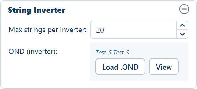
The card's file row reads No OND file loaded beside Load .OND and
View. Click Load .OND and, in the Load Inverter OND File dialog,
pick the .OND file — the PVsyst inverter file the manufacturer publishes for
the machine you intend to buy. The row then shows the manufacturer and model,
and View becomes available.
The file settles the AC side of the design:
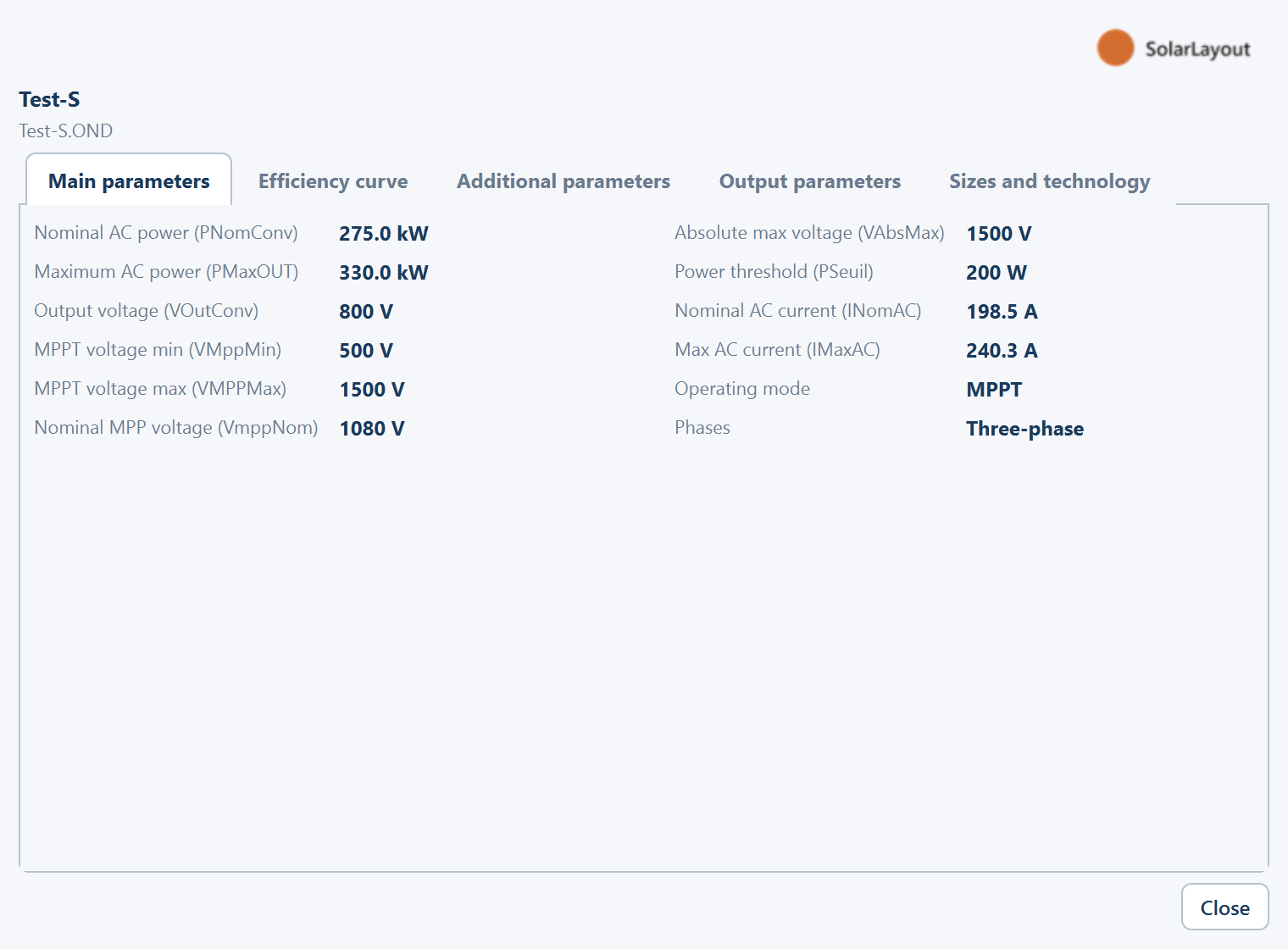
- The maximum AC output drives the plant AC capacity. The application takes
the file's maximum output power as the rating of one machine and reports the
plant's AC capacity from it — the AC capacity (MWac) and Inverter
capacity (MW) rows of the Summary view, and the Plant AC Capacity line of
the bill of materials, which reads
—until an inverter file is loaded. - The DC / AC ratio follows. With a DC capacity from the placed modules and an AC capacity from the file, the ratio is reported on the DC / AC ratio row. It is the number a reviewer looks at first, and without an inverter file there is nothing to divide by.
- When the file declares no maximum output, the nominal power is used instead. Some files carry only a nominal rating; the design still sizes, from that figure.
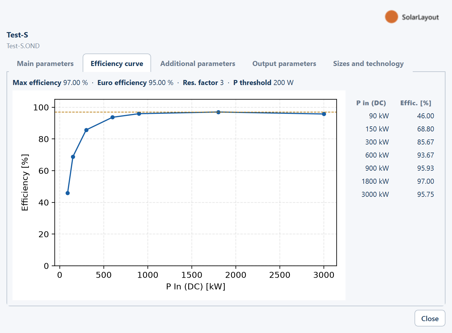
Loading an inverter file does not set the inverter efficiency used in the energy calculation. The String / Central Inverter efficiency field on the Yield tab stays at whatever you entered; read the file's efficiency curve (below) and set that field yourself. See Loss assumptions.
Viewing what was read
View opens the file read-only in a window titled Inverter (OND) followed by the file name, laid out the way PVsyst presents it, so you can confirm the machine before designing around it. It has five tabs: Main parameters, Efficiency curve, Additional parameters, Output parameters and Sizes and technology.
The Efficiency curve tab draws efficiency against load from the points in the file. Read it against the inverter loading your DC / AC ratio implies: a plant run at a high ratio spends most of its hours in the upper part of that curve, and the conversion loss you enter in the yield calculation should agree with what the curve shows there.
The file is also what makes string sizing possible
The number of modules you may wire in series is bounded by the inverter's tracking voltage window — the range of DC voltage over which the inverter can hold the maximum power point (MPPT — maximum power point tracking). That window is a property of the machine, and the application reads it from the inverter file. With no inverter file loaded there is no window, and therefore nothing to size a string against: the Size… button on the Array tab asks for one before it opens the calculator.
This is why the module file and the inverter file are usually loaded together at the start of a session. Both are also required by Simulation with AC capacity, which sizes the plant backwards from a target AC figure using the same two files.
Where to go next
String sizing
How many modules go in series, and the three limits that decide it
Cables
Switching cable routing on, and the allowances added to the DC string-cable total
Control rooms
How the ICR block capacity sets the number and position of control rooms
Simulation with AC capacity
Sizing the plant from a target AC capacity and DC / AC ratio instead
Topography
Keeping tables off ground that is inside the boundary but too steep, too uneven or too low-lying to carry a structure.
Cables
The Cables card on the Electrical tab — whether cable runs are routed and measured, the performance notice, and the three allowances added to the DC string-cable total.