Module specifications
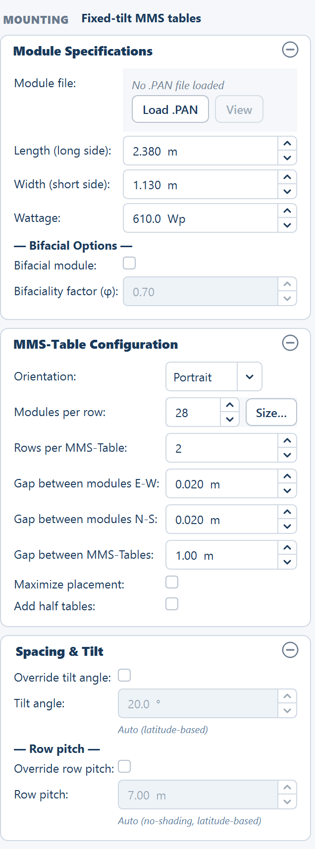
Module dimensions, wattage and bifacial settings on the Array tab, and what loading a manufacturer .PAN file fills in for you.
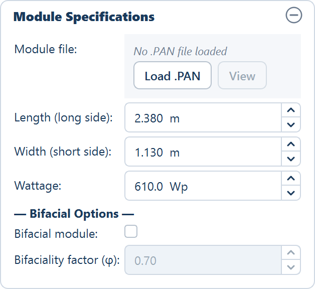
The Module Specifications card describes the single PV module every other dimension in the plant is built from. Table size follows from the module dimensions, row pitch follows from table size, string length follows from the module's electrical data, and plant DC capacity is the placed module count multiplied by the wattage entered here. Get this card wrong and every figure downstream is wrong with it.
You can type the three numbers by hand from a datasheet, or load the
manufacturer's .PAN file and have them filled in — along with the electrical
data the energy model and the string-sizing calculator need, which a datasheet
reading would not give you.
Where it sits
The card is the first one on the Array tab, directly under the read-only MOUNTING chip that records the mounting chosen at launch — Fixed-tilt MMS tables or Single-axis tracker. The cards below it depend on that choice: a fixed-tilt design shows MMS-Table Configuration and Spacing & Tilt; a tracker design shows Tracker Configuration instead. Every card on the tab can be folded with the button in its header.
The fields
| Field | Default | Range | What it does |
|---|---|---|---|
| Length (long side) | 2.38 m | 0.5–5.0 m | The module's long edge. Becomes the north–south or the east–west dimension of the module depending on orientation. |
| Width (short side) | 1.13 m | 0.5–3.0 m | The module's short edge, on the other axis. |
| Wattage | 610 Wp | 100–1000 Wp | Nameplate power at standard test conditions (STC). Multiplies the placed module count into plant DC capacity. |
| Bifacial module | off | — | Turns on the rear-side energy contribution and enables the bifaciality factor. |
| Bifaciality factor (φ) | 0.70 | 0.50–0.95 | Rear-side efficiency as a fraction of front-side efficiency. Editable only when Bifacial module is ticked. |
Above the fields, the file row reads No .PAN file loaded beside two buttons, Load .PAN and View; View is enabled once a file has been read.
All internal geometry is held in metres, projected to the site's own UTM zone, so the two dimensions are metres regardless of what the manufacturer's datasheet uses.
Length is the long side, width the short side
The two fields are named by the module itself, not by the compass. Length is always the long edge of the glass; Width is always the short edge. Neither field is tied to east–west or north–south on its own.
Which edge ends up running east–west is decided by the mounting orientation, one card further down the tab:
- On a fixed-tilt plant, Portrait puts the module's short side east–west and its long side north–south. Landscape reverses that. See Table configuration.
- On a tracker plant, P config (Portrait) puts the module's long side east–west, across the torque tube. L config (Landscape) puts the long edge north–south, along the tube. See Tracker configuration.
The practical consequence: swapping orientation does not change the module, but it does change the table's east–west width and north–south height, and therefore the row pitch, the ground coverage ratio and how many tables fit on the site.
Enter the module's own dimensions here, never a table dimension or a pre-multiplied figure. The application multiplies the module out into the table for you, and doing it twice inflates capacity silently.
Loading a manufacturer file
Load .PAN reads a .PAN module file — the module data file published for
PVsyst — and fills the card in from it. This is the reliable route: it brings
in electrical parameters that have no field on the tab but that the energy
model and the string-sizing calculator use.
Click Load .PAN
The Select PVsyst Module File dialog opens. Pick the .PAN file for the
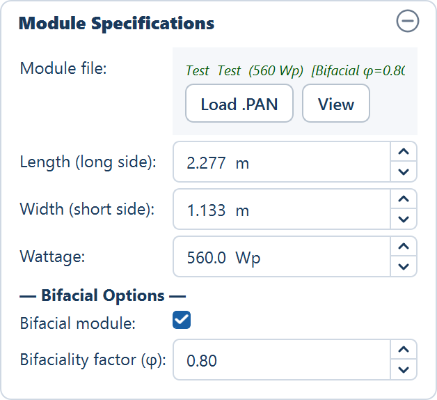
module you are designing around. The file row then shows the module's name in
green, and View becomes available. Hover over the name for the figures the
file carried that have no field of their own — the power temperature
coefficient, the nominal operating cell temperature and, when the file declares
one, Bifacial detected φ = ….
Check the filled-in values
Wattage, long side and short side are overwritten with the file's values, and a bifacial declaration ticks the box and fills the factor. Compare them against your datasheet before going further.
Size the string when you are ready
Loading the file asks nothing further. When you want the number of modules in series worked out from this module's voltages, click Size… beside Modules per row on the MMS-Table Configuration card (or beside Modules per string (N–S) on the Tracker Configuration card). The calculator needs an inverter file as well as this one — see String sizing.
What the file fills in
| Filled in from the file | Where it lands |
|---|---|
| Wattage | Wattage on this card |
| Long side and short side | Length (long side) and Width (short side) |
| Bifacial declaration | Ticks Bifacial module and fills Bifaciality factor (φ) |
| Temperature coefficient of maximum power | The temperature loss on the Yield tab, recomputed |
| Nominal operating cell temperature | The NOCT field in the String sizing window |
| Voltage temperature coefficient | The coefficient the String sizing window works from |
A file that declares the module bifacial turns the checkbox on for you and fills the factor with the manufacturer's value, so you do not have to know whether a given part number is bifacial to get the rear-side gain modelled.
Loading a file also recomputes Temperature losses on the Yield tab and replaces the shipped default with a figure derived from this module. That calculation needs the module's temperature coefficient of maximum power, which is read from the file rather than typed anywhere. The module operating temperature it derives is displayed next to the loss row, with the working shown underneath it — see Temperature losses.
The nominal operating cell temperature comes from the file too
The nominal operating cell temperature — NOCT, the cell temperature the module reaches under standard nominal conditions — is read from the module file as well, and it is the figure the hot case of string sizing works from. A file that declares no NOCT falls back to 45 °C, and the String sizing window marks its NOCT field as estimated so you know the figure did not come from the manufacturer.
So the electrical data behind string sizing is not only the voltages: the cell temperature the voltages are evaluated at travels with the file too. Typing the three dimensions by hand leaves no voltages at all to size from.
Metres or millimetres
Module files are published in both units. Dimension values are accepted either way and interpreted by magnitude: a value below 100 is read as metres, a value of 100 or more is read as millimetres. The same module described in metres and described in millimetres therefore lands as the same long side, and you do not have to convert anything before loading.
Viewing what the file contains
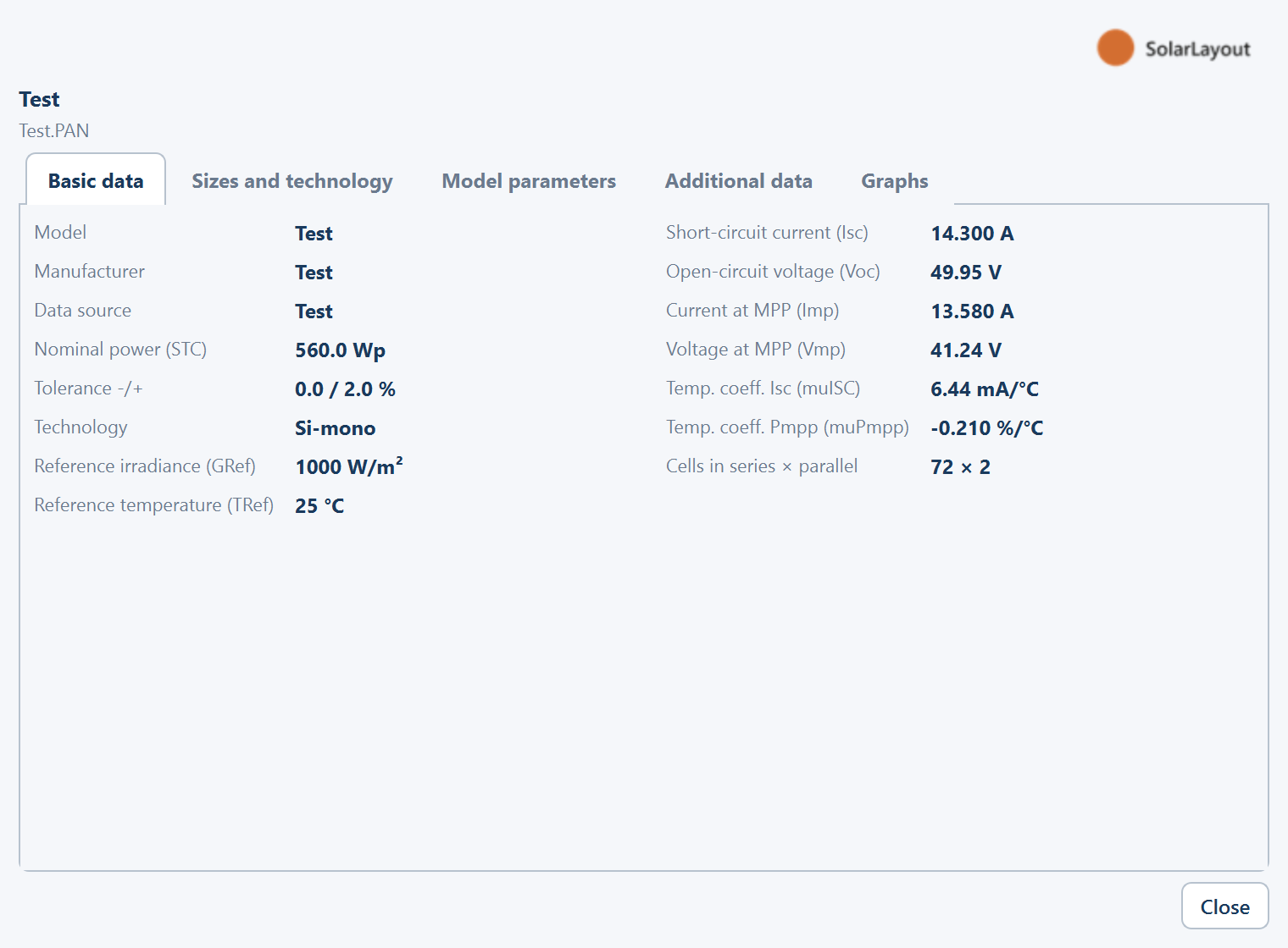
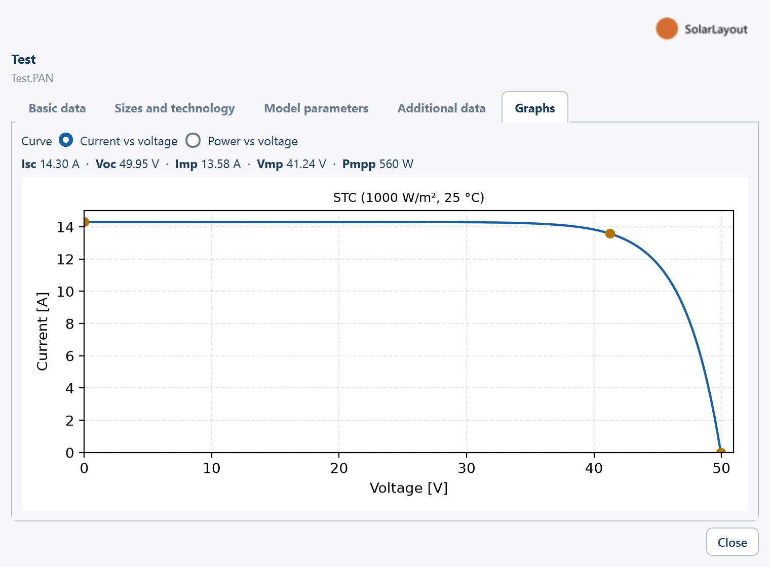
View opens a read-only window titled Module (PAN) followed by the file name, showing everything read from the file. Nothing in it is editable — it exists so you can confirm you loaded the module you meant to, and check parameters the tab has no field for.
| Tab | What it shows |
|---|---|
| Basic data | Nameplate figures and the STC operating point |
| Sizes and technology | Physical dimensions and cell technology |
| Model parameters | The one-diode model parameters and temperature coefficients |
| Additional data | Remaining declared values |
| Graphs | The current–voltage and power–voltage curves, titled STC (1000 W/m², 25 °C) |
The Graphs tab is the quickest sanity check on a file from an unfamiliar source: a curve with the expected knee near the maximum power point tells you the electrical data read cleanly.
Bifacial options
A bifacial module generates from light reaching its rear face as well as its front. Two controls at the bottom of the card decide whether that is modelled.
Bifacial module is off as shipped. With it off, the module is treated as monofacial and no rear-side energy is added, whatever the module actually is. Tick it — or load a file that declares bifaciality — and the rear-side gain enters the yield calculation.
What the bifaciality factor means
Bifaciality factor (φ) is the rear-side efficiency of the module expressed as a fraction of its front-side efficiency. A factor of 0.70 means the rear face converts light to power at 70 % of the efficiency of the front face, so a given irradiance falling on the back is worth 70 % of the same irradiance falling on the front.
- Typical published values sit between 0.65 and 0.80. The field accepts 0.50–0.95, and ships at 0.70.
- The factor is a property of the module, not of the site. Take it from the
datasheet or let a
.PANfile fill it in; do not tune it to reach a target yield. - Typical bifacial energy gain over the same plant built with monofacial modules is 5–15 %. Where a specific design lands in that band depends far more on the ground under the array and on how densely the rows are packed than on the factor itself.
Ground albedo lives on the Yield tab
The factor alone cannot produce a rear-side figure. The rear irradiance the model uses depends on the ground reflectance — the albedo — the tilt of the module, and the ground coverage ratio, because closely packed rows leave less lit ground between them to reflect anything. Only then is the result scaled by φ.
Ground albedo (ρ) is therefore set on the Yield tab, not here, and defaults to 0.25. The full rear-side model, and what to set albedo to for different ground cover, is on Bifacial gain.
What moves when these fields move
Nothing on this card is local to it. Before you change a value on a design you have already reviewed, know what else changes with it.
| Change | What it moves |
|---|---|
| Length or Width | The table's east–west width and north–south height, and through them the automatic row pitch, the ground coverage ratio, and how many tables fit inside the usable area |
| Wattage | Plant DC capacity, and therefore the number of inverter control rooms — one per capacity block — and the DC / AC ratio |
| Bifacial module, Bifaciality factor (φ) | Energy yield only. Neither field moves a single table; the layout is identical with the checkbox on or off |
A module dimension change is a layout change, so the layout has to be generated again before any figure in the Summary view is trustworthy. A bifacial change is an energy change, so the energy calculation has to be run again, but the placed layout stands.
If you have no module file
Typing the three fields by hand is a complete input for layout purposes — the placement, the table geometry, the capacity and the Summary view all work from the dimensions and the wattage alone. What you lose is the electrical data behind two calculations:
- The string-sizing calculator has no voltages to work from. Size… answers with Module PAN file required and sends you back to Load .PAN, so the number of modules in series stays a value you enter.
- The temperature loss stays at its default percentage instead of being derived from this module's coefficient.
Both are usable defaults, not blockers. Load a file when you have one.
Where to go next
Image boundaries
Tracing a plant boundary from a scan, a screenshot or an exported picture, and setting the scale in the Site reference window that turns pixels into metres.
Table configuration
The MMS table — orientation, modules per row, rows per table, gaps, and the two options that change how tables are packed.