Bifacial modules
How SolarLayout models rear-side production for bifacial modules, and how to configure the inputs.
A bifacial module generates electricity from both faces — front-side from direct sunlight, rear-side from light reflected off the ground. SolarLayout adds the rear-side contribution to your energy yield when the module is marked as bifacial.
How the rear-side contribution is calculated
The rear-side production is driven by two main inputs:
- Bifaciality factor (φ) — the module's rear-side efficiency relative to its front-side efficiency. A bifaciality factor of 0.75 means the rear face is 75% as efficient as the front face for the same irradiance.
- Ground albedo (ρ) — the fraction of incoming sunlight that the ground reflects back upward. Grass reflects ~0.20; sand or light-coloured concrete reflects 0.30–0.40; snow can exceed 0.70.
SolarLayout uses a simplified view-factor model that combines these with your layout's tilt and ground-coverage ratio (GCR) to estimate the annual rear-side irradiance reaching the back of each table.
The bifacial gain is capped at 20% as a sanity bound — values above that almost always indicate a misconfigured input rather than a real site.
Typical inputs
| Input | Typical range | Notes |
|---|---|---|
| Bifaciality factor (φ) | 0.65 – 0.85 | Auto-filled from the module's PAN file; check the datasheet otherwise |
| Ground albedo (bare earth / grass) | 0.18 – 0.22 | Typical value |
| Ground albedo (light-coloured) | 0.30 – 0.40 | White gravel, light concrete, or sand |
| Ground albedo (snow) | 0.60 – 0.80 | Not relevant for utility-scale |
The shipped default for ground albedo is 0.25 — a midpoint that works for most ground-mount sites until you have a site-specific value. Tune it to match what's actually under your tables.
How much extra yield to expect
Typical bifacial gain on utility-scale fixed-tilt: 5–12% over the annual yield. Higher tilt + higher ground albedo + lower GCR push it toward the top of that range; lower tilt and denser packing push it toward the bottom.
Bifacial gain is not free in design terms — taller mounting structures and slightly wider row spacing usually accompany a bifacial design, both of which have BoM and land cost implications that the yield uplift has to outweigh.
How to configure bifacial in SolarLayout
Pick a bifacial module
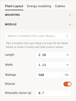
Open the Plant Layout tab and find the Module section. Pick a bifacial module you've uploaded under Resource Library, or upload a bifacial PAN file first. Your library starts empty until you upload your own PAN files (or your org's admin has curated a few "Managed" entries). See PAN files for the PAN import flow.
When you pick a bifacial PAN, the Bifacial switch flips on automatically and the bifaciality factor (φ) is filled from the file. While a PAN is pinned, the Bifacial switch and φ are display-only — clear the picker (the X in the module combobox) to switch to manual mode, where you can flip the switch and set φ by hand. The default φ when toggled on by hand is 0.70.
Set ground albedo for the site
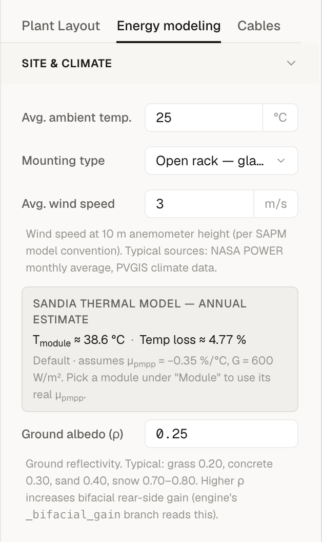
In the Energy modeling tab, open the Site & Climate section and set the Ground albedo (ρ) value. The shipped default is 0.25.
Lower the value (e.g., 0.20) for grass / bare earth; raise it (e.g., 0.30–0.40) for light gravel, white concrete or sand.
Generate layout
Click Generate layout (it reads Generate layout again once a layout exists). The energy result now includes the rear-side contribution. The bifacial gain percentage is reported in the exported PDF energy report (Page 3 / Energy parameters, shown only for bifacial modules) so you can see how much of the total yield comes from the back face.
Reading the bifacial breakdown in your energy report
The exported PDF energy report includes a Bifacial gain row on Page 3 (Energy parameters) — the percentage uplift the rear-side contribution adds on top of the front-side yield (capped at 20%). It appears only when the module is bifacial. The yearly and lifetime energy figures in the report already include this uplift; the gain percentage is shown alongside so you can sense-check it and report it separately for lender diligence.
The in-app Energy yield tab shows the headline metrics (Year-1 energy, P50/P75/P90, PR, CUF, specific yield, and the monthly and 25-year curves) but does not break out the bifacial gain on screen — for that figure, export the PDF report.