Exporting the diagram
Three routes out of the SLD view — the report's diagram page, a standalone PDF of the sheet, and a CAD drawing whose symbols are real entities.
A finished single-line diagram — SLD — leaves the application by three routes. All three write the same sheet, frame and all; what differs is what the receiving end can do with it.
| Route | How | What you get |
|---|---|---|
| The report's diagram page | Export ▾ ▸ Export Detailed Project Report in the view header | The diagram as the Single Line Diagram annexure of the Word document; the same page is in Export PDF (with Piles) |
| A standalone PDF | ⬇ Export SLD to PDF on the SLD TOOLS panel | The sheet on its own, as a PDF |
| A CAD drawing | ⬇ Export SLD to DWG on the SLD TOOLS panel | The sheet as a drawing file, with the symbols written as real CAD entities |
The two SLD buttons sit at the foot of the tools panel, which takes over the left column while the SLD tab is up. The Export ▾ menu sits beside Save project in every view. See Building the single-line diagram.
The diagram page in the report
The Detailed Project Report carries the diagram automatically. You do not export it separately: build the diagram, then choose Export ▾ ▸ Export Detailed Project Report, and the diagram is written in as the Single Line Diagram annexure — after the Site Layout Plan and the Design Summary, before the Bill of Materials. The document is A3 landscape throughout, so the diagram page and the layout drawing come out on the same paper. The full content order is on The Detailed Project Report.
While the pile overlay is on, Export ▾ ▸ Export PDF (with Piles) writes a PDF report whose third page is the same diagram sheet.
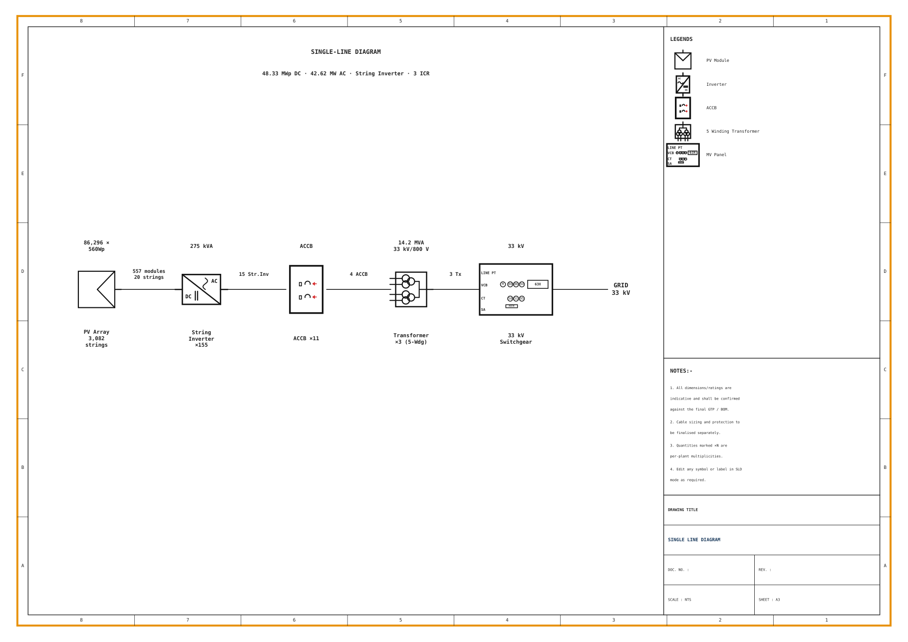
One behaviour to know about in the PDF with piles: if the diagram fails to draw, that page is skipped silently and the rest of the report is still produced. A report is never lost because of a problem with the diagram. The consequence for you is that a missing diagram page is not announced — so if the diagram matters to the document, open the file and confirm the page is there.
A standalone PDF of the sheet
⬇ Export SLD to PDF writes the sheet as a PDF on its own.
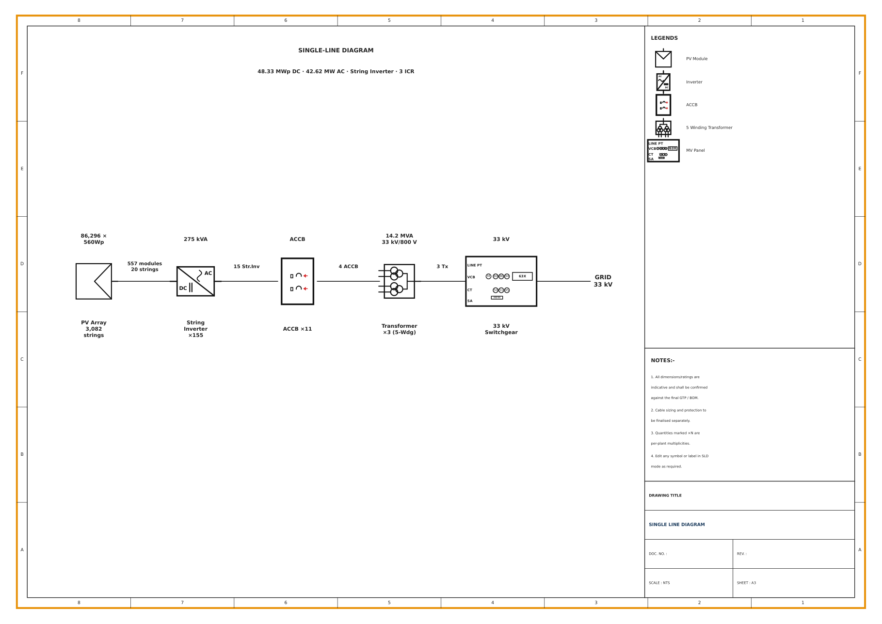
This is the review copy. It carries the border, the zone grid, the legend band and the title block, so a reviewer can mark it up against a zone reference and hand it back, and it needs nothing but a PDF reader at the far end.
The sheet is written at A3 proportions. For a large plant the physical paper size grows — A3, then A1, then A0 — while those proportions hold, so a long chain is printed on bigger paper rather than being squeezed into A3.
A CAD drawing
⬇ Export SLD to DWG writes the sheet as a drawing file for a drafting team.
Which format you actually get
A .dxf file is always written. It is converted to .dwg only when the ODA
File Converter is installed on the machine; with no converter present, the
export stays .dxf.
So expect one of two outcomes, and check which one you got:
| On the machine | What you get |
|---|---|
| The ODA File Converter is installed | A .dwg file |
| It is not installed | A .dxf file |
Neither is a failure. .dxf is a CAD interchange format that every serious
CAD program reads, so a .dxf export is usable as it stands — and if your
drawing office wants .dwg specifically, converting one file at their end is a
smaller job than debugging an export. Look at the extension of the file you
produced before sending it, so that nobody downstream is surprised.
The symbols come across as geometry, not as a picture
This is the point of the CAD route. Each symbol's shape is written into the drawing file as real CAD entities, rotated as it sits on screen. The result is a drawing a drafter can select, move, copy and edit — not an image of your screen dropped into a drawing frame.
Practically: the diagram you see is the diagram they open. A transformer placed already rotated to line up with the bus arrives rotated the same way, and a symbol you turned with ⟲ 90° or a typed angle arrives at that angle.
The same holds for a symbol you traced yourself. An imported image symbol is stored as outlines rather than as a picture, which is why it too exports as real geometry. See Importing diagrams and custom symbols.
The one exception is an imported background. A diagram brought in with 📄 Import PDF / DXF is a picture on the sheet, so it stays a picture — it cannot become CAD geometry. If the CAD file is the deliverable, redraw the imported content with palette symbols, or accept that only what you drew on top arrives as geometry.
The sheet frame comes across too
The outer border, the inner frame, the zone grid, the legend band and the title block are all in the CAD file, in the same positions they occupy on screen.
That matters more than it sounds. A drafting team receiving the diagram alone would have to drop it into their own frame and re-letter the zones; receiving the framed sheet, they can work on the drawing itself. Anything you typed into the title block with 📝 Text travels with it — and anything you left blank arrives blank.
Exporting is not saving
All three routes produce a document for somebody else. None of them is how you keep the diagram.
The diagram is part of the session, and the session is saved as a project file. A saved project holds the inputs, the layout, the hand edits, the diagram and the materials list together, so reopening it brings the diagram back exactly as you left it — editable, on the same sheet. Save the project as well as exporting, or the next revision starts from the PDF you sent out. See Projects.
Which route to use when
| You are sending it to | Use | Why |
|---|---|---|
| A bid or tender pack | The report's diagram page | One document carries the drawing, the summary, the materials list and the energy figures together |
| A reviewer or an internal approval | ⬇ Export SLD to PDF | The sheet on its own, with the zone grid to refer to, openable by anyone |
| A drafting office or a detailed-design team | ⬇ Export SLD to DWG | Real entities they can edit, inside the sheet frame |
If you are unsure, send the standalone PDF for agreement and the CAD file for work. The PDF settles what the diagram says; the drawing file is what somebody builds on.
Before you export
Check the ratings and the equipment
The automatic build's annotations come from the bill of materials and the topology rules, not from your purchase order. Read them once more. See Building a diagram from the plant.
Fill in the legend, the notes and the title block
All three ship blank. A drawing issued with an empty title block is a drawing nobody can file.
Fit the sheet
Use ⤢ Fit so you are looking at the whole sheet, and check that nothing sits outside the frame.
Export, then open what you exported
Confirm the diagram page is present in the report, and check the extension of the CAD file.
Where to go next
The Detailed Project Report
Where the diagram page sits, and what every other section carries
CAD drawing export
The layout's own drawing file and its layers
Building the single-line diagram
The sheet, the tools, and the title block you fill in
Importing diagrams and custom symbols
Why a background stays a picture and a traced symbol does not
Importing diagrams and custom symbols
Bringing an existing diagram in as a background to draw over, and tracing your own image into a vector symbol that exports to CAD as real geometry.
Bill of materials
The BOM view — the materials list computed from the placed layout, its five columns, the BOM TOOLS panel, every line item it can carry, and how it reaches the report and the exports.