Symbol reference
Every symbol the SLD TOOLS palette carries, grouped by what it does — generation, AC distribution, transformers, protection and instrumentation.
The SLD TOOLS panel holds the symbols a single-line diagram — SLD — is drawn from. Placing one takes two clicks: click the symbol button, then click the sheet where it goes. The symbol lands at that point and becomes an element you can select, move, rotate, group, copy or delete like any other. The tools that do all of that are on Building the single-line diagram.
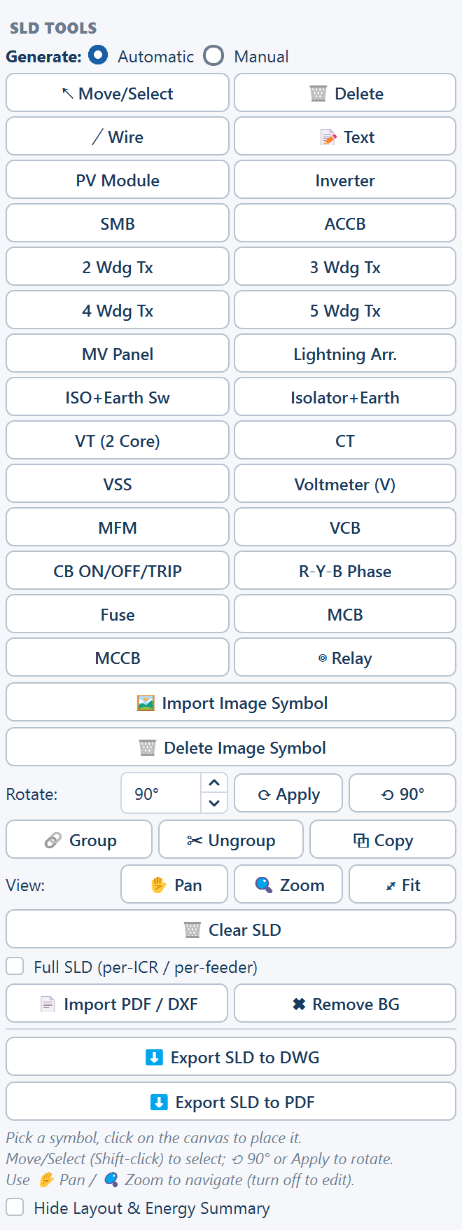
The names below are the palette's own names, so you can read this page with the panel open beside it. The buttons sit in a two-column grid, the four drawing tools first — ↖ Move/Select, 🗑 Delete, ╱ Wire, 📝 Text — then the symbols. They are grouped here by what the equipment does, which is not the order the buttons sit in.
Placing a symbol
Click the symbol
One click on the palette button arms that symbol. Nothing is placed yet.
Click the sheet
The symbol lands where you click. Place it roughly — position is easier to correct than to get right first time.
Position and orient it
Switch to ↖ Move/Select to drag it into place, and use ⟲ 90° or a typed angle with ⟳ Apply if it needs turning.
Wire it in
Use ╱ Wire to connect it to the bus or to the device beside it.
Label it
Use 📝 Text to write the tag and the rating beside the symbol. A symbol carries its shape and its position; everything printed next to it is text you add.
Generation and conversion
The DC end of the plant, and the machine that turns DC into AC.
| Symbol | What it represents |
|---|---|
| PV Module | The photovoltaic modules — drawn once for a string, an array or the whole DC field, depending on how much of the plant the diagram is showing |
| Inverter | The inverter that converts DC to AC. In a string-inverter design this is the machine standing out in the field; in a central-inverter design it is the machine inside the control room |
| SMB | A string monitoring box — the field enclosure that collects strings and passes their combined DC output on to a central inverter without converting it |
Which of the last two your diagram needs follows from the inverter choice you made at launch. A string-inverter plant has no string monitoring boxes; a central-inverter plant has both, with the boxes in the field and the inverters in the control room. See Choosing a design mode.
AC distribution
Where the converted output is gathered and where the medium-voltage side begins.
| Symbol | What it represents |
|---|---|
| ACCB | An AC combiner box — the breaker panel a group of inverters lands on |
| MV Panel | A medium-voltage panel, the switchgear the transformer feeds and the point the outgoing line leaves from |
Transformers
Four transformer symbols, differing in how many windings they show. Pick the one that matches the machine on the drawing rather than the one that looks closest.
| Symbol | What it represents |
|---|---|
| 2 Wdg Tx | A two-winding transformer — one primary, one secondary |
| 3 Wdg Tx | A three-winding transformer — the usual inverter duty transformer, IDT, taking the inverter output up to medium voltage with two low-voltage windings on one core |
| 4 Wdg Tx | A four-winding transformer, for a machine taking more low-voltage inputs onto a single core |
| 5 Wdg Tx | A five-winding transformer, the same arrangement extended again |
The winding count is the whole distinction, and it is the part of an SLD an electrical reviewer reads first. A plant whose inverters are paired onto two-input machines and one whose inverters land four to a machine have the same capacity and different drawings.
Protection and switching
The devices that isolate, interrupt and protect. This is the largest group in the palette, and the group that most of a real SLD is made of.
| Symbol | What it represents |
|---|---|
| Lightning Arr. | A lightning arrester — LA — the surge-diverting device on the line |
| ISO+Earth Sw | An isolator with an earth switch, drawn as one device |
| Isolator+Earth | An isolator with its earth connection |
| VCB | A vacuum circuit breaker |
| MCCB | A moulded-case circuit breaker |
| MCB | A miniature circuit breaker |
| Fuse | A fuse |
| ⊚ Relay | A protection relay. Placing it asks for the ANSI device number — the protection function number, such as 50 or 51, that identifies the relay on the drawing |
Two isolator symbols are offered because the two are not the same drawing. The first shows the isolator and its earth switch as a combined device; the second shows the isolator with its earth connection. Choose per the arrangement your drawing standard expects, and use one of them consistently across the sheet.
The three breaker symbols are distinguished by type, not by rating. The rating is something you write beside the symbol with the 📝 Text tool — a breaker symbol carries no rating of its own.
Instrumentation and indication
Measurement, metering and the indication a control panel carries.
| Symbol | What it represents |
|---|---|
| CT | A current transformer — stepping line current down to a measurable value for metering and protection |
| VT (2 Core) | A voltage transformer with two cores, one for metering and one for protection |
| Voltmeter (V) | A voltmeter |
| VSS | A voltmeter selector switch — the switch that points one voltmeter at each phase pair in turn |
| MFM | A multi-function meter, reading voltage, current, power, power factor and energy in one instrument |
| CB ON/OFF/TRIP | Circuit-breaker status indication — the on, off and trip lamps |
| R-Y-B Phase | Phase indication for the three phases, labelled R, Y and B |
Instrument transformers and the instruments they feed are drawn as separate symbols, wired together, because that is how the panel is built: the current transformer sits on the line and the meter sits on the panel door. Draw the transformer on the run, the instrument beside it, and connect them with ╱ Wire.
Which symbols arrive pre-rotated
The Inverter and every transformer are placed pre-rotated to 270°, so that they line up with the horizontal bus the rest of the diagram is built along. This holds in both electrical topologies.
Every other symbol in the palette is placed as it is drawn on its button. If one needs turning — an arrester on a vertical drop, a breaker across the bus rather than along it — select it and use the Rotate row.
A symbol that looks turned the moment you place it is almost always an inverter or a transformer, and almost always correct. Check it against the bus before rotating it back.
The rows under the symbols
Below the symbol grid the panel carries the controls that act on what you have placed:
| Row | Controls | What they do |
|---|---|---|
| Rotate | an angle field (0–360°, steps of 15°, 90° to begin with), ⟳ Apply, ⟲ 90° | Turn the selection by the typed angle, or by a quarter turn |
| Group | 🔗 Group, ✂ Ungroup, ⧉ Copy | Bind a selection into one element, release it, or duplicate it |
| View | ✋ Pan, 🔍 Zoom, ⤢ Fit | Move around the sheet; turn Pan or Zoom off to edit again |
The image-symbol buttons, the import and export buttons, the Full SLD option and 🗑 Clear SLD sit on the same panel; each is covered on the page that owns it.
The symbols the automatic build places
Generate: Automatic draws a chain from a small part of this palette — the equipment whose counts and ratings it can read from the plant. Which symbols it uses depends on the electrical topology:
| Topology | Symbols in the chain |
|---|---|
| String inverter | PV Module, Inverter, ACCB, a transformer, MV Panel, and the grid |
| Central inverter | PV Module, SMB, Inverter, a transformer, MV Panel, and the grid |
Everything else on this page — the isolators, the breakers, the instrument transformers, the meters and the indication — is yours to add on top of that chain. That is the normal way round: the automatic build settles the equipment count and the connection order, and the protection and metering detail is drawing work. See Building a diagram from the plant.
When the symbol you need is not here
The palette covers the equipment a PV plant's SLD normally shows. For anything else — a make-specific device, a customer's own block symbol, a standard symbol your drawing office uses — import it with 🖼 Import Image Symbol. An imported image is traced into a vector symbol rather than pasted as a picture, so it draws as line art and exports to CAD as real geometry, and it stays available for later sessions. Imported symbols appear in the grid after the built-in ones.
See Importing diagrams and custom symbols.
Where to go next
Building the single-line diagram
The sheet, the drawing tools, rotation, grouping and copying
Building a diagram from the plant
Which of these symbols the automatic build places, and in what order
Importing diagrams and custom symbols
Adding a symbol the palette does not carry
Exporting the diagram
How symbol shapes reach a CAD file as real entities
Building the single-line diagram
The SLD view — the A3 drawing sheet, the Generate choice, the drawing tools, and how the finished diagram reaches the project report, a standalone PDF and a CAD file.
Building a diagram from the plant
Generate: Automatic draws a starter single-line diagram from the plant's own equipment counts and the materials list's ratings; Full SLD expands it to one feeder per control room.