The main window
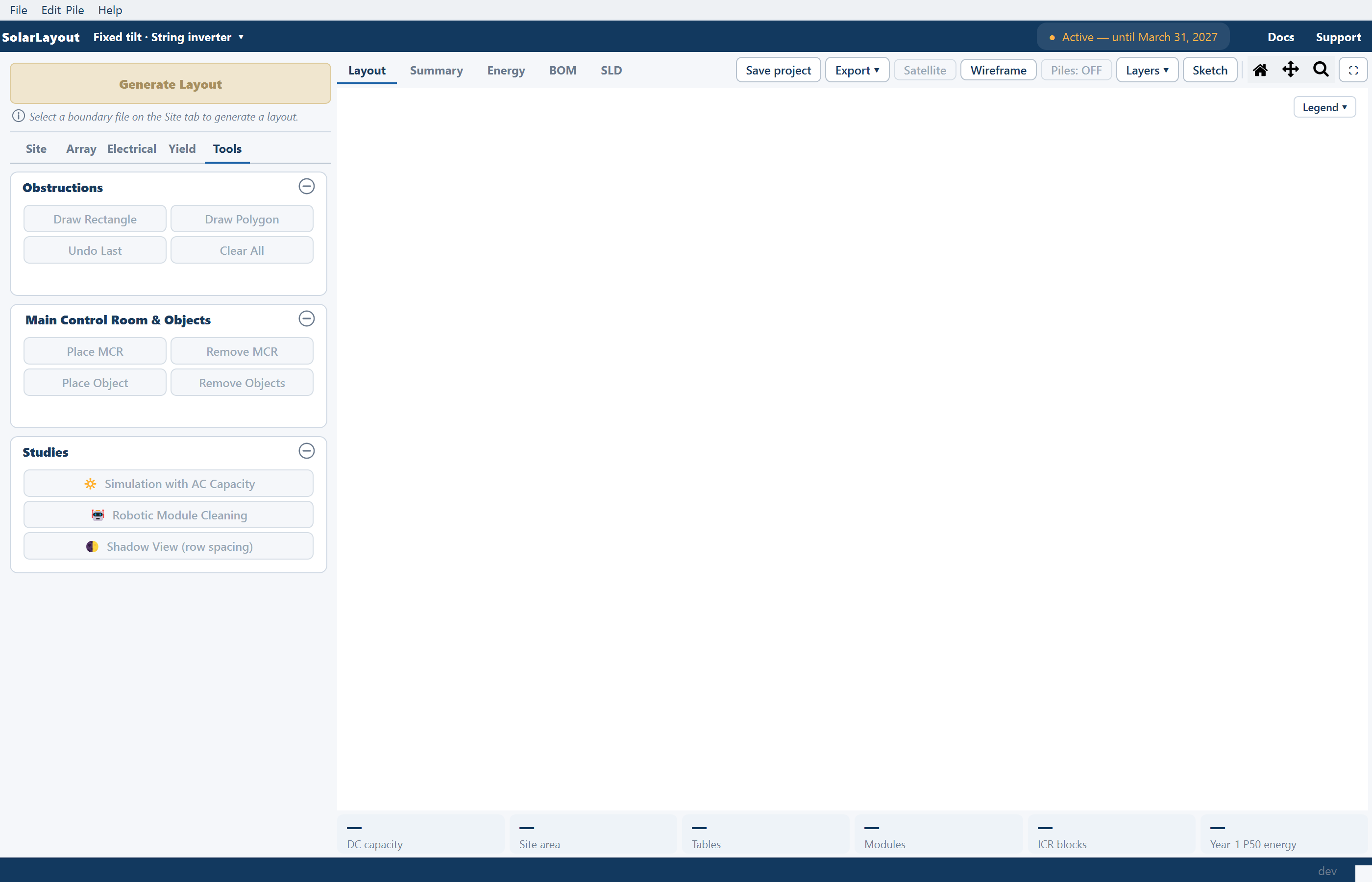
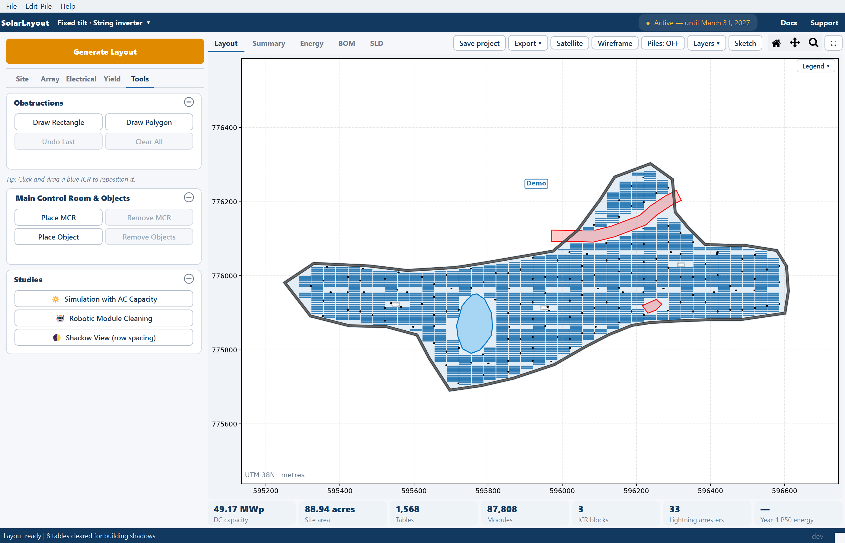
The ribbon, the pinned Generate Layout button, the five stage tabs of inputs on the left, the views on the right, and the status bar.
The main window has three parts. A navy ribbon runs across the top. The left column holds the pinned Generate Layout button and, under it, every design input on five stage tabs. The right side shows the plant — the drawing, the summary sheet, the energy result, the bill of materials and the single-line diagram — as five views of the same design, with a row of plant totals under whichever view is up.
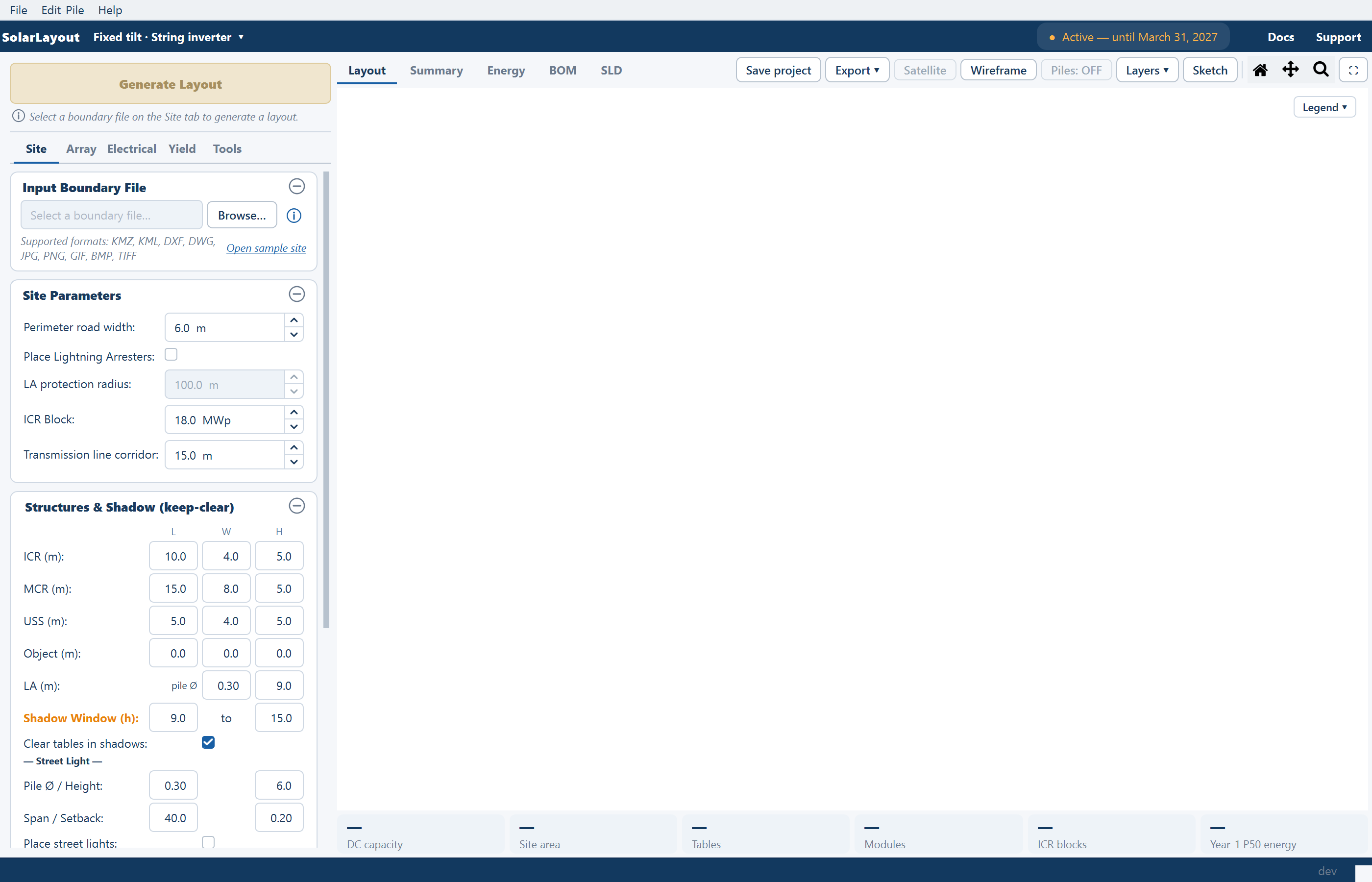
Above the ribbon sits a conventional menu bar — File, Edit-Pile and Help — for projects, the pile editor, the in-app guide and the licence window. Below everything, a status bar reports what the application is doing.
The ribbon

| Item | What it is |
|---|---|
| SolarLayout | The brand. The window title beside it names the design, for example SolarLayout [Fixed Tilt | String Inverter]. |
| The design chip | Reads the design this window holds — Fixed tilt · String inverter ▾, Tracker · Central inverter ▾ and so on. Clicking it opens the New design window and launches a second, independent window for the design you choose there; this window stays open. See Choosing a design mode. |
| The status mirror | A gold italic line that repeats the status bar's message, so a result is readable without looking down. |
| The access chip | ● Active — until <date> when this device has access, with (offline) appended while a cached check is in use; ● Access expired or ● Access revoked in red with a Contact Us button; ● Access status unavailable when the server cannot be reached. With no access at all the chip is hidden and a gold Get Free Access button stands in its place. See Activate your licence. |
| Docs | Opens this documentation site in your browser. |
| Support | Opens the Support / Feedback window. See Getting help. |
The left column
Generate Layout
The gold Generate Layout button (F5) is pinned above the tabs, so it is in the same place whichever tab you are on. Under it a hint line says why it is disabled — "Select a boundary file on the Site tab to generate a layout." until a boundary file is chosen. Generating needs active access for this device; without it the License / Subscription window opens instead.
The five stage tabs
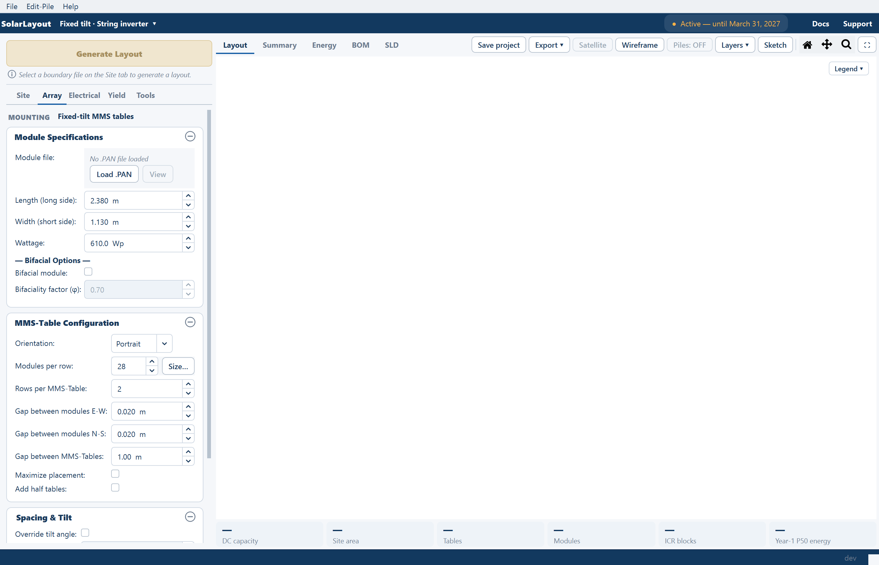
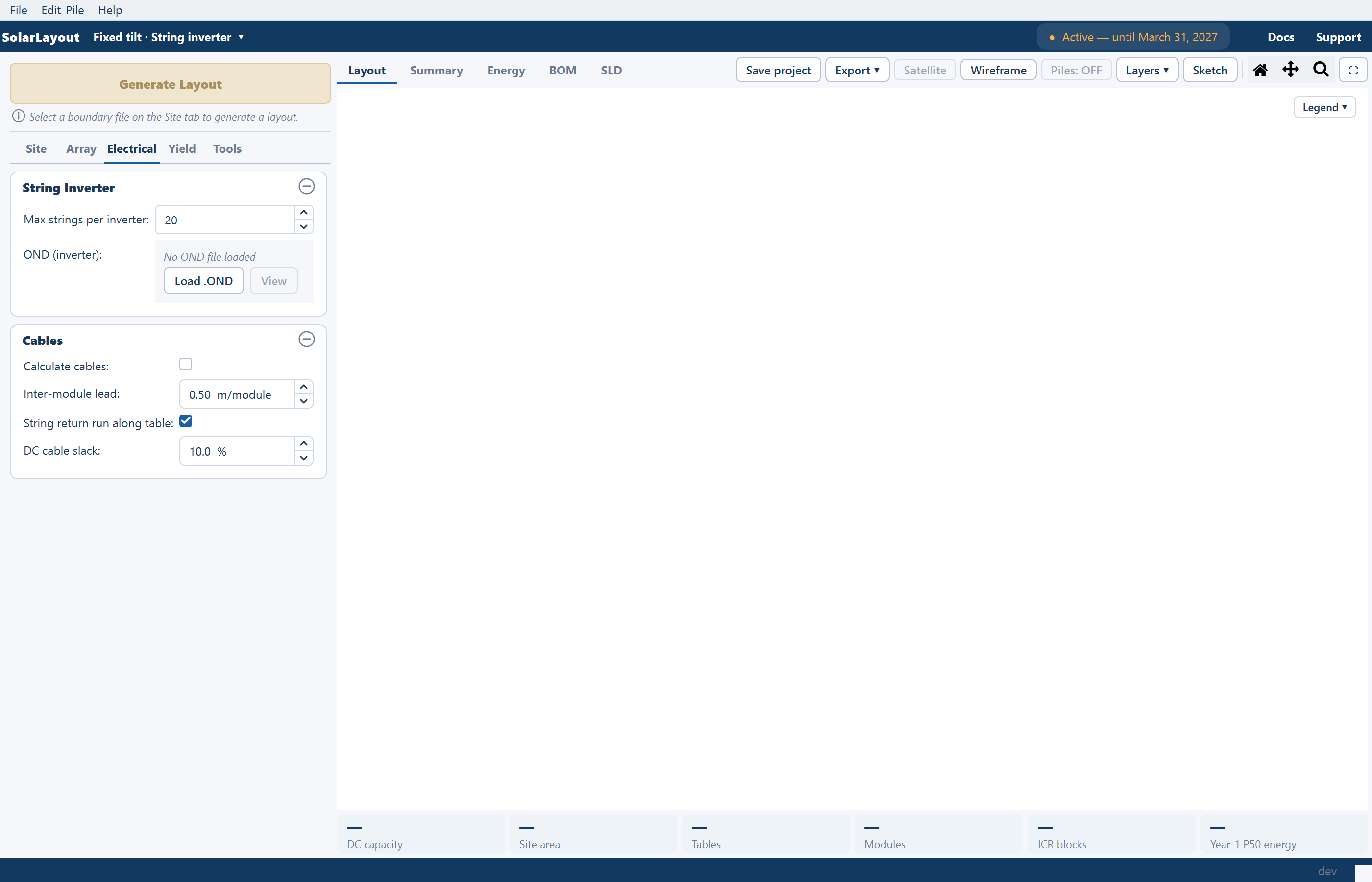
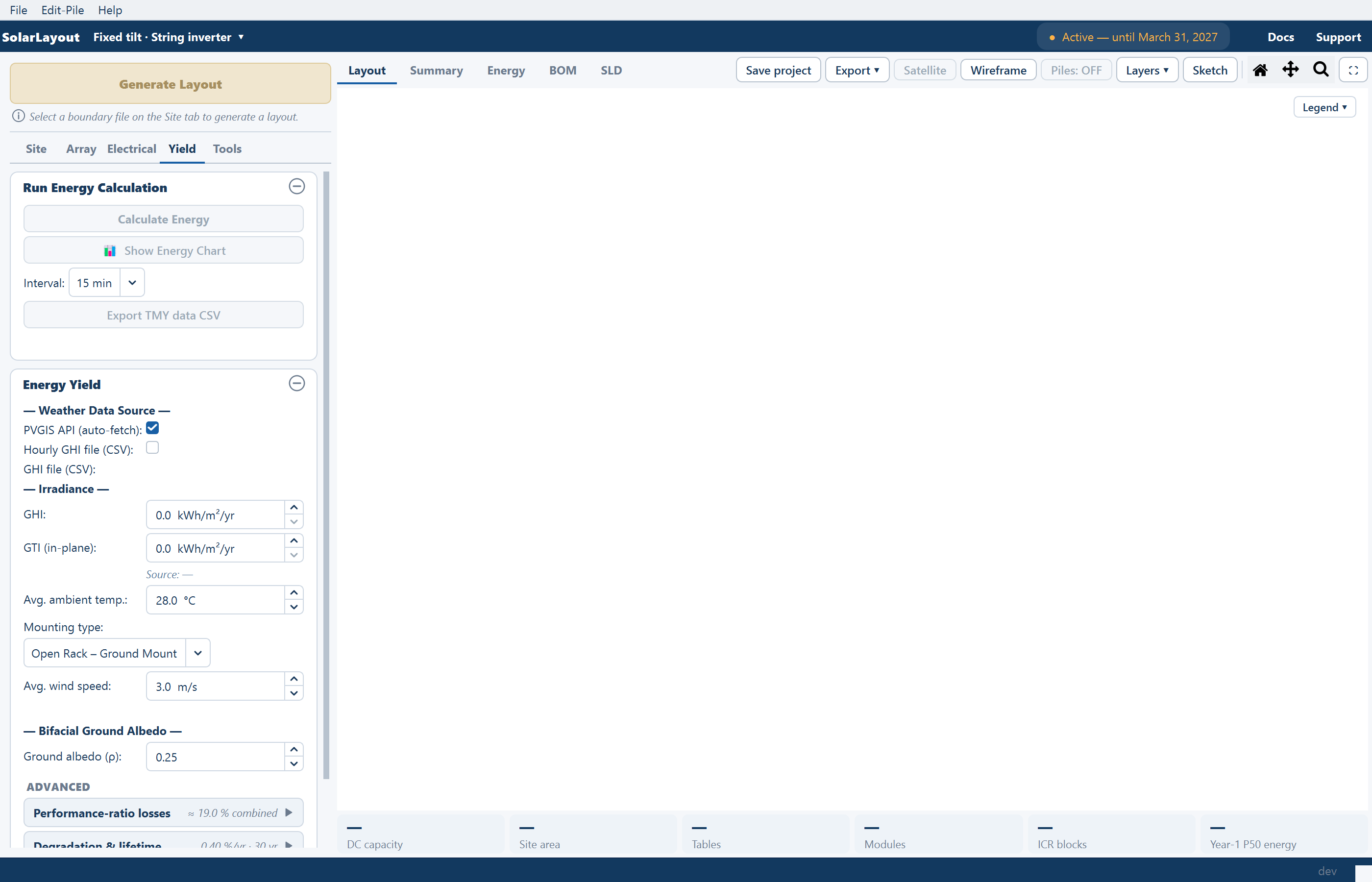
The inputs are split across five tabs, in the order the design is normally worked through. Every card on a tab is a collapsible group: the ⊖ button in its header folds it away, and every card opens expanded.
| Tab | Cards, top to bottom | Covers |
|---|---|---|
| Site | Input Boundary File · Site Parameters · Structures & Shadow (keep-clear) · Topography (slope-aware exclusion) | The boundary file; roads, arresters, ICR blocks and the transmission line corridor; keep-clear shadows; terrain — Boundary files, Site parameters |
| Array | A read-only MOUNTING chip · Module Specifications · then MMS-Table Configuration and Spacing & Tilt on a fixed-tilt design, or Tracker Configuration on a tracker | The module, the table or tracker geometry, tilt and pitch — Module, Table configuration, Tracker |
| Electrical | String Inverter (or SMB – String Monitoring Box on a central-inverter design) · Cables | Strings per inverter, the inverter file, and cable calculation with its allowances — Inverter, Cables |
| Yield | Run Energy Calculation · Energy Yield | The energy run, the weather source, site conditions, losses, degradation and exceedance probabilities — How yield is calculated |
| Tools | Obstructions · Main Control Room & Objects · Studies | Editing a generated layout: hand-drawn obstructions, the main control room and placed objects, and the three studies — Obstructions, Site equipment, Sizing from an AC capacity |
The MOUNTING chip on the Array tab reads Fixed-tilt MMS tables or Single-axis tracker. It is a reminder, not a control: the mounting was chosen in the New design window, and a different mounting means another window.
The Tools tab is locked until a layout exists — its tooltip reads "Generate a layout first" and every button on it is disabled. Between the Obstructions card and the Main Control Room card it carries the reminder "Tip: Click and drag a blue ICR to reposition it.", which is how a control room is moved: with no navigation tool active, drag it to a valid spot inside the perimeter road and release.
The mode banner
Three tools take the whole left column over while they are on: Sketch (hand editing of the drawing), and the SLD and BOM views. Each replaces the pinned button with a coloured banner — orange ● Sketch Mode, blue ● SLD Preparation, green ● Bill of Materials — carrying its own Exit button, and swaps the stage tabs for the tool's palette. Leaving the mode gives the column back exactly as it was. See Sketch Mode, Single-line diagram and Bill of materials.
The right side
Five tabs across the top — Layout · Summary · Energy · BOM · SLD — are views of one plant, and each takes the whole area under the header. To the right of the tabs sits the row of tools for the current view: Save project and Export ▾ always; the drawing's view toggles, the Layers ▾ popover, Sketch, the navigation icons and the expand button on the Layout view; Copy and Open in window on Summary and Energy. Under every view runs a single row of plant chips — the plant totals, and the only place they are shown.
Views, layers and tools covers each view, every tool and the Layers rows in full.
The status bar
| Left | Right |
|---|---|
| Progress and result messages — "Calculating layout…", "Layout ready" with the notes that apply, "KMZ exported: …", "Project saved (full): …" and the like. The ribbon's status mirror repeats them. | The live cursor position over the drawing, in UTM metres, and the application version (for example v1.2.0) — the number to quote when you report a problem. |
The status bar never carries the plant totals; those are in the plant chips.
Where to go next
Choosing a design mode
The New design window — fixed tilt or tracker, string or central inverter — what each choice means, what it changes in the interface, and how to open a second design.
Views, layers and tools
The five views of the plant, the tools beside the view tabs, the Layers popover, the plant chips, and the Summary and Energy views.